
Date:2026-04-24 Categories:Product Subsitution Hits:531 From:Guangdong Youfeng Microelectronics Co., Ltd
This article is from Charging Head. If there is any infringement, please contact the author for prompt removal
Preface
Charging Head Network purchased a solar mini grid-connected inverter, manufactured by Dongguan Xineng Technology Co., Ltd., with the model number GMI180L. The inverter features an aluminum alloy casing for efficient heat dissipation. One side of the housing is equipped with a mounting hook and a working indicator light, while the other side has terminal blocks. The AC output uses dedicated terminals, and the DC input employs MC4 connectors.
The inverter has a rated output voltage of 230VAC, supports an output voltage range of 180-280V, and is compatible with 50/60Hz frequencies. The DC input voltage range is 10.8-30V, with a maximum input power of 180W and a rated output power of 150W. Below is the disassembly of this solar micro grid-connected inverter, showcasing its internal design and component materials.
Appearance of New Energy Technology GMI180L Solar Micro Grid Inverter.
The label is printed with the input and output specifications, safety precautions, and wiring methods of the inverter.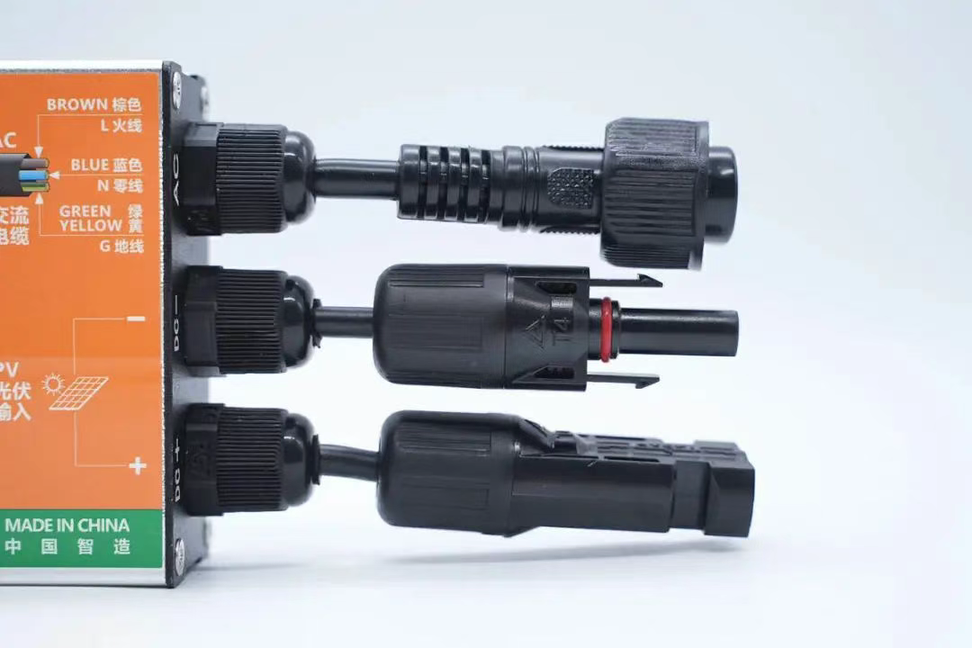
The upper right side is the AC output terminal block, and the lower side is the DC MC4 connector.
The side cover plate is printed with the definition of the wiring terminal.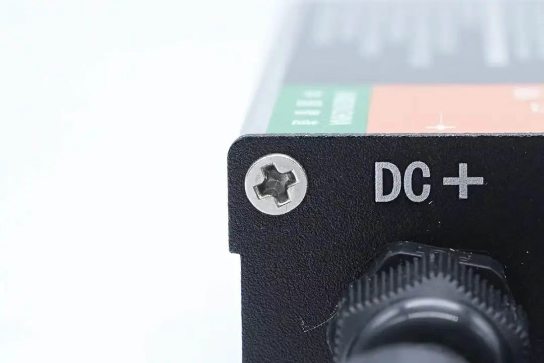
The cover plate is fixed by screws.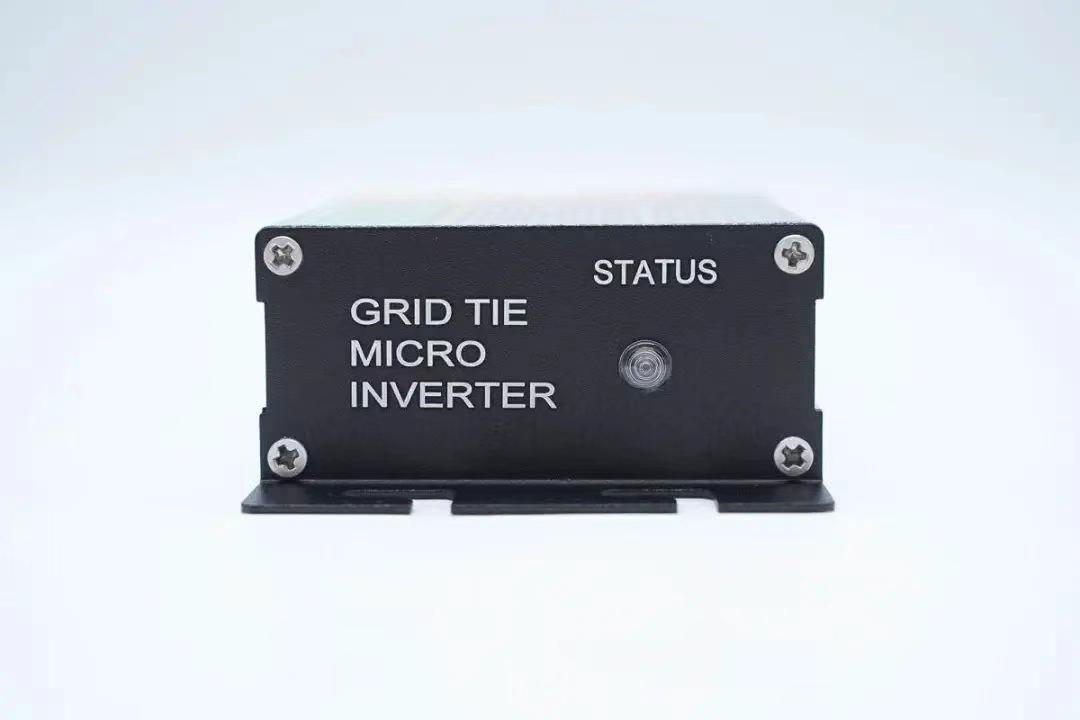
The other side cover is equipped with a work indicator light.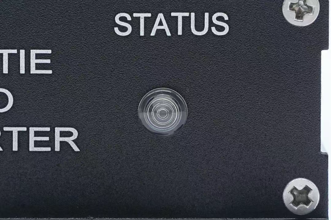
Close up of work indicator light.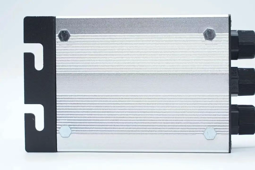
The inverter housing is equipped with nuts to secure the internal PCBA module.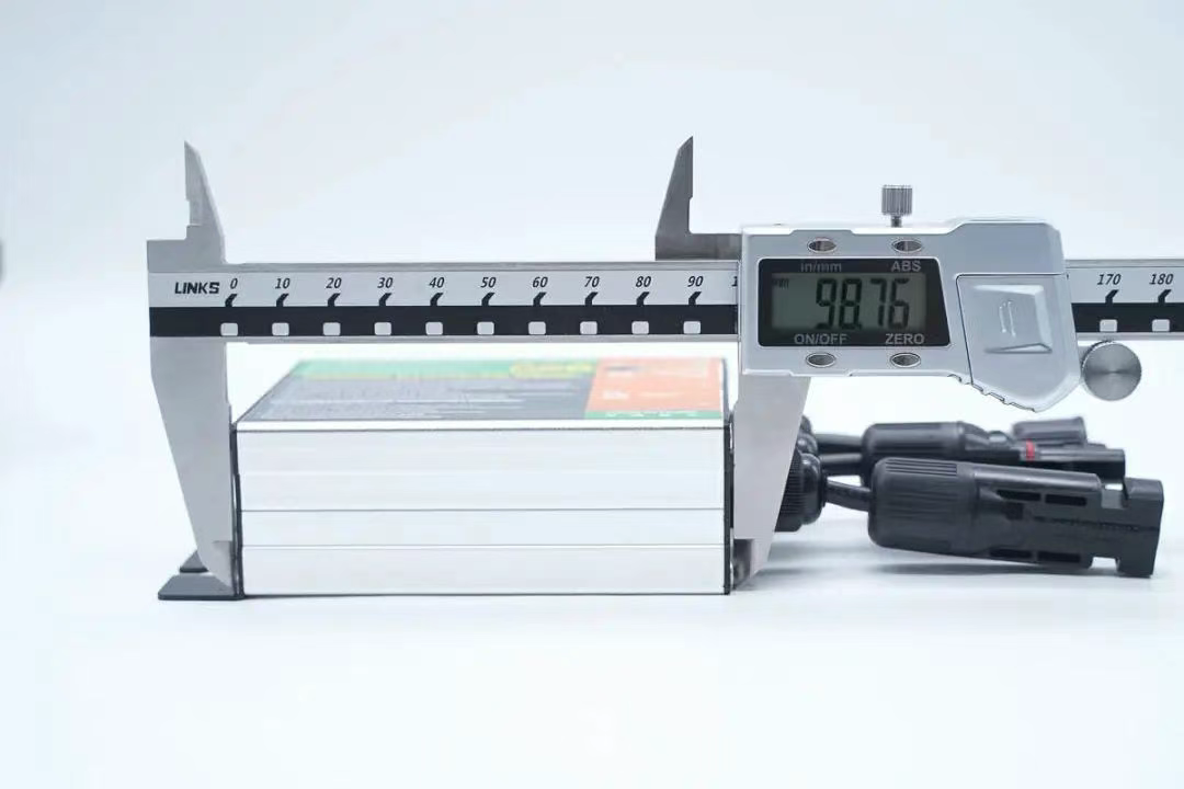
The length of the inverter housing was measured to be approximately 98.8mm.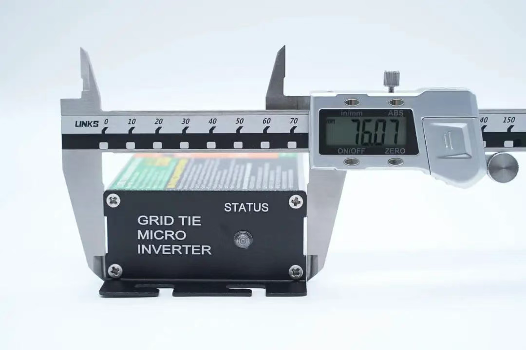
The width of the shell is approximately 76.1mm.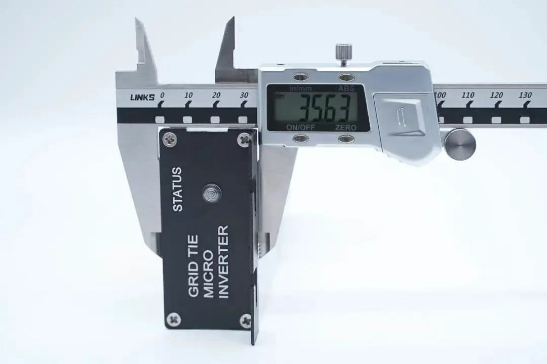
The thickness of the shell is approximately 35.6mm.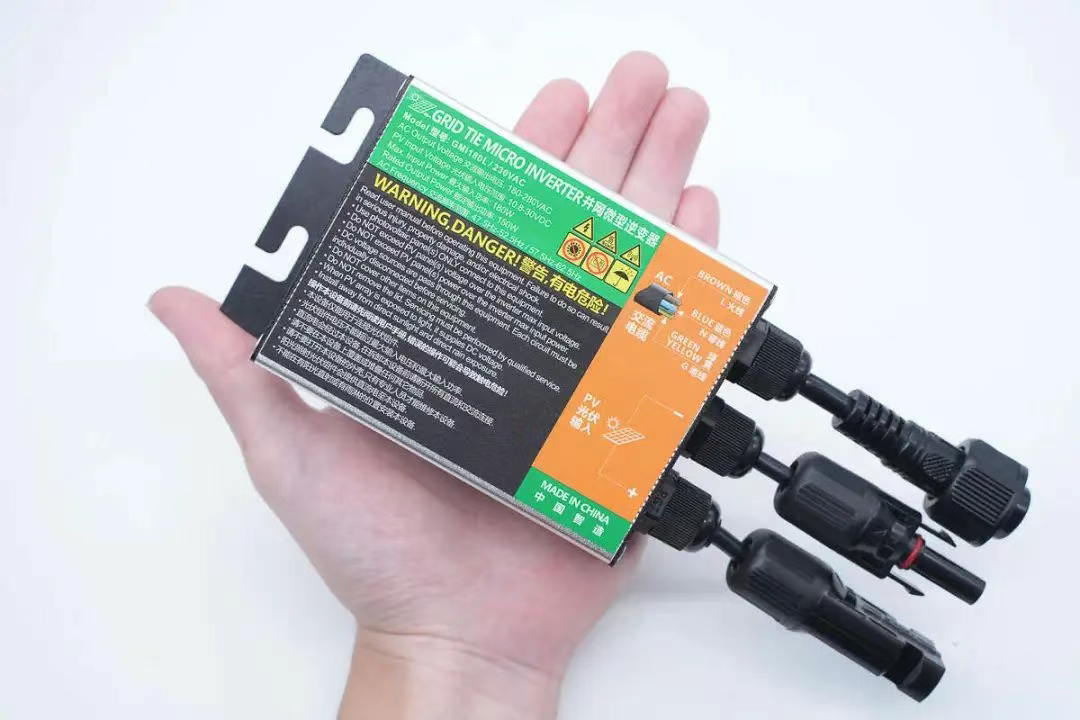
The size of the product in the hand is intuitively felt.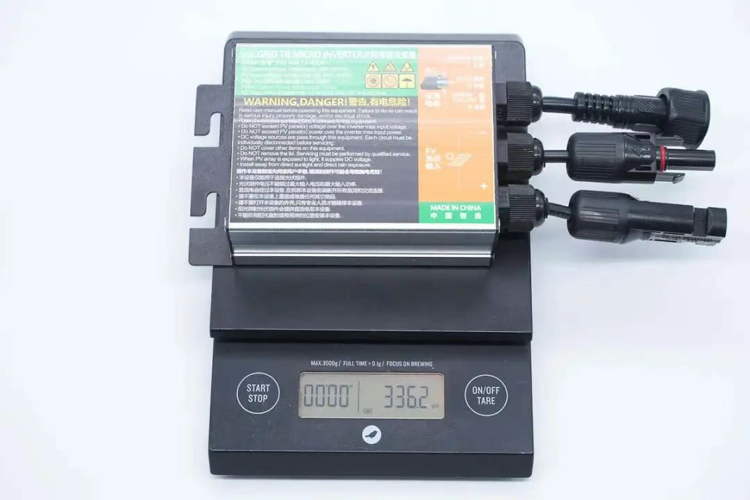
The net weight of the inverter was measured to be approximately 336.2g.
New Energy Technology GMI180L Solar Micro Grid Inverter Disassembly.
After seeing the appearance display of this inverter, let's disassemble it and take a look at the internal design and materials together.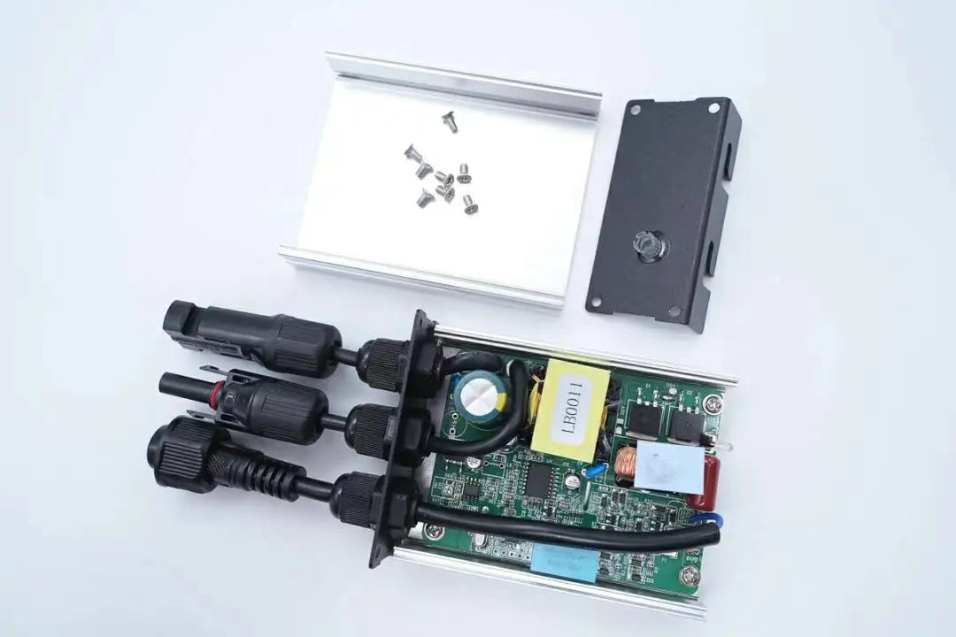
Firstly, unscrew the fixing screws on both sides of the casing and disassemble the inverter casing.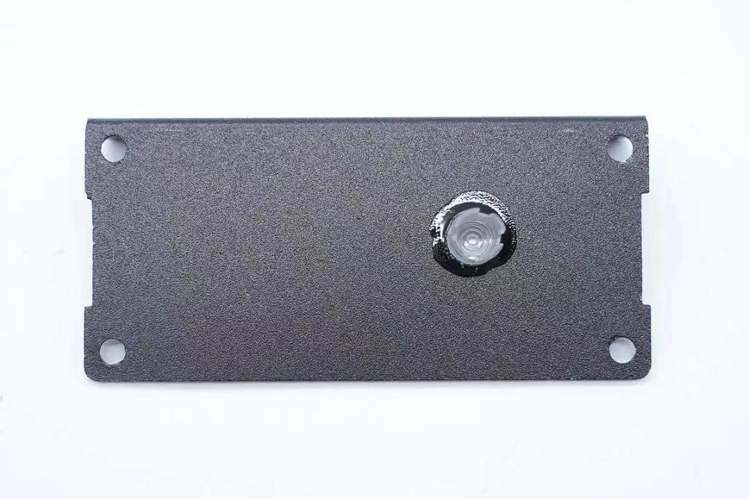
Stick the indicator light guide column inside the cover plate.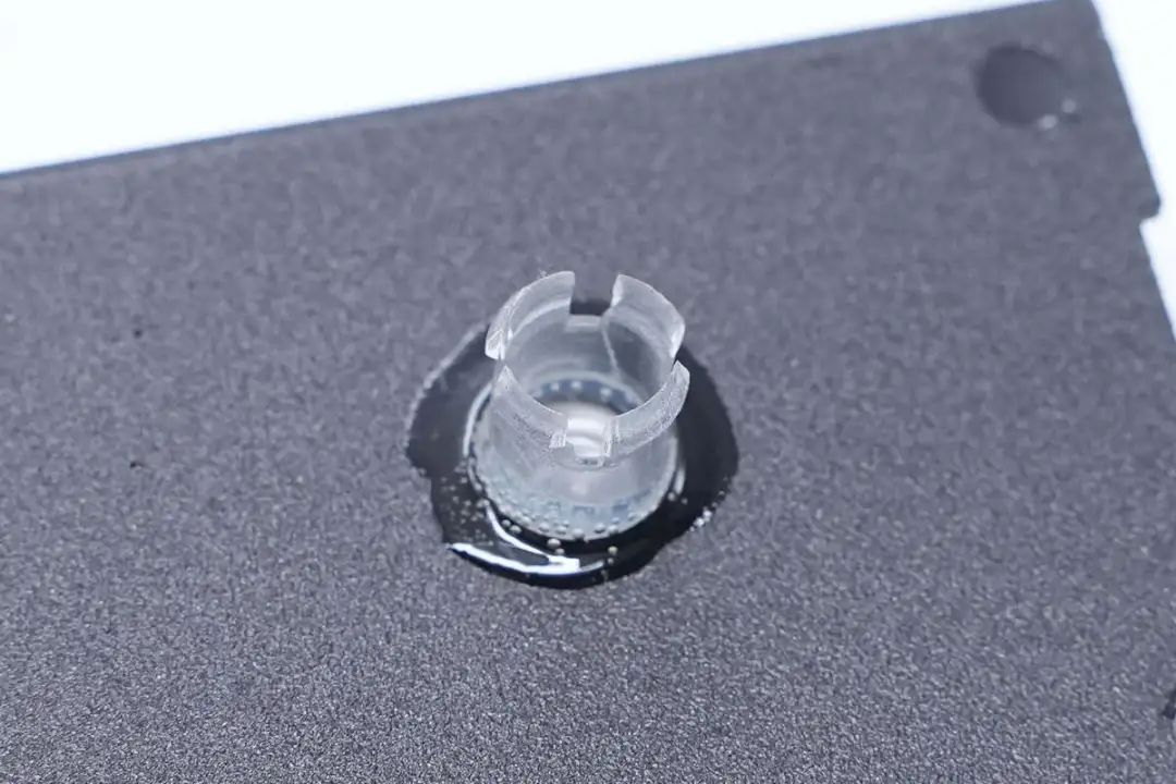
Close up of indicator light guide column.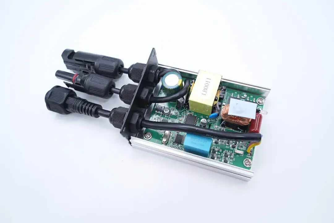
The PCBA module is fixed to the inside of the housing by screws.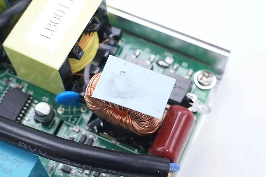
The filter inductor is attached with a thermal pad in contact with the housing, which serves to fix and dissipate heat.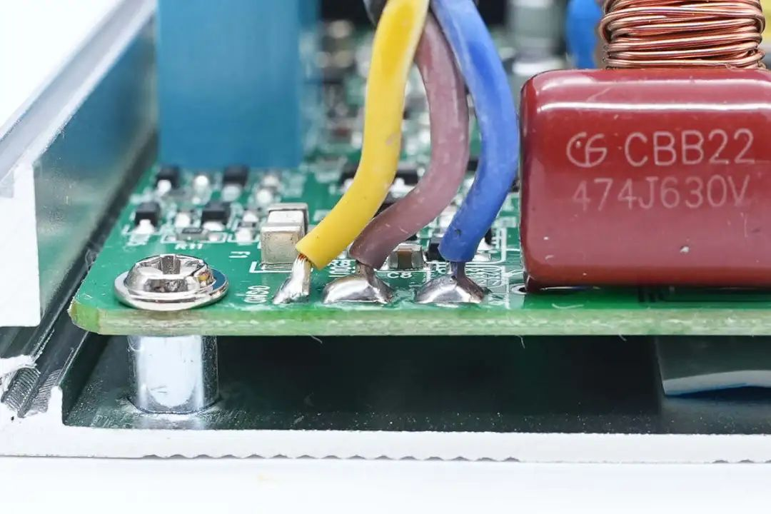
The output wires of the inverter are connected by welding.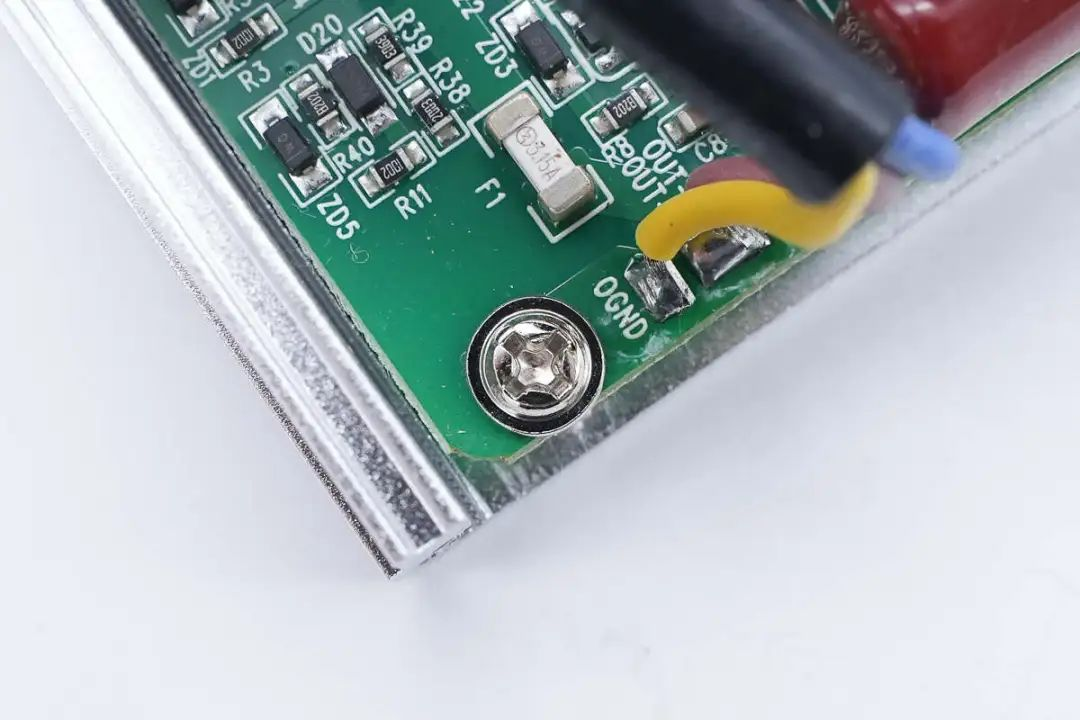
Close up of screws fixing PCBA module.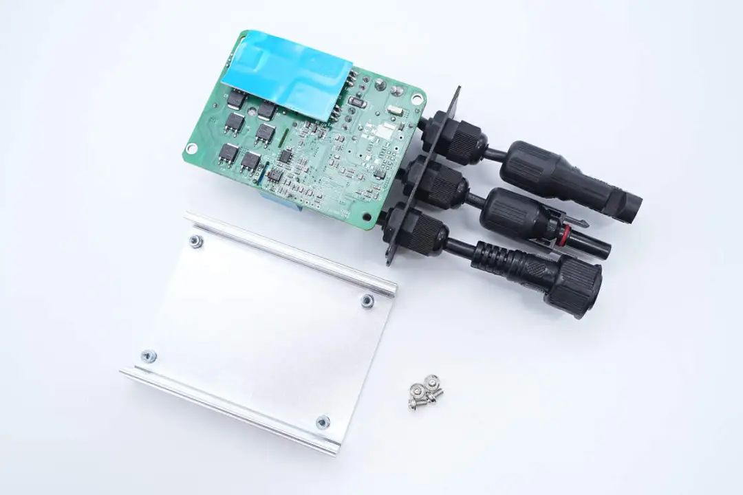
Unscrew the fixing screws and remove the PCBA module. There is also a thermal pad between the power device and the housing for heat dissipation.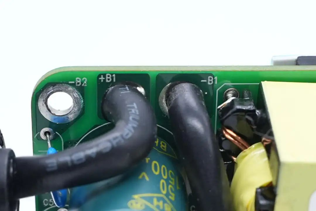
Welding connection of DC positive and negative input wires.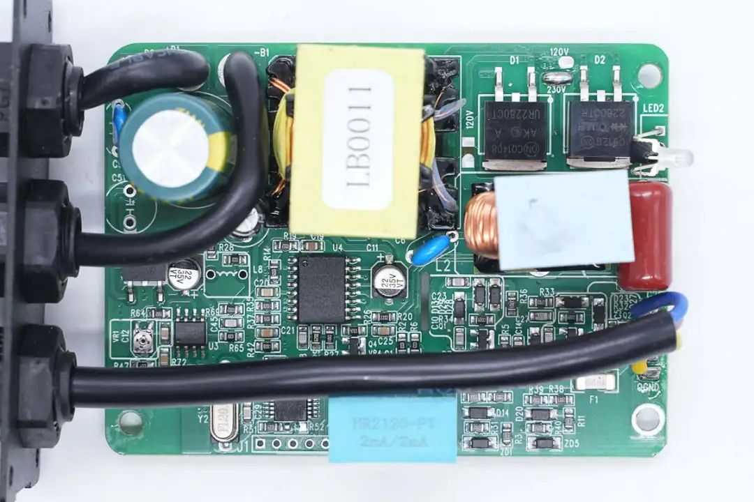
Front view of PCBA module, with a filter electrolytic capacitor soldered in the upper left corner and a transformer, rectifier diode, filter inductor, and filter capacitor soldered in the right corner. Weld a three terminal voltage regulator chip and operational amplifier below the electrolytic capacitor, MCU, Isolate driver chips, transformers, and other components.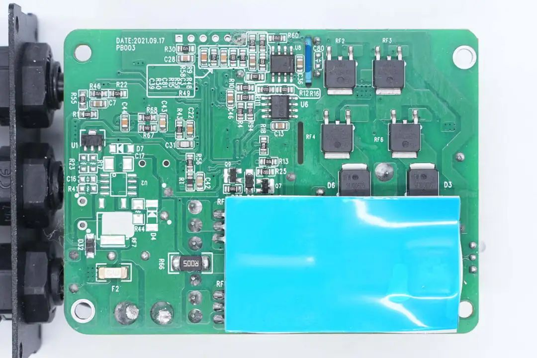
On the back of the PCBA module, there is a blue thermal pad located at the corresponding power device position.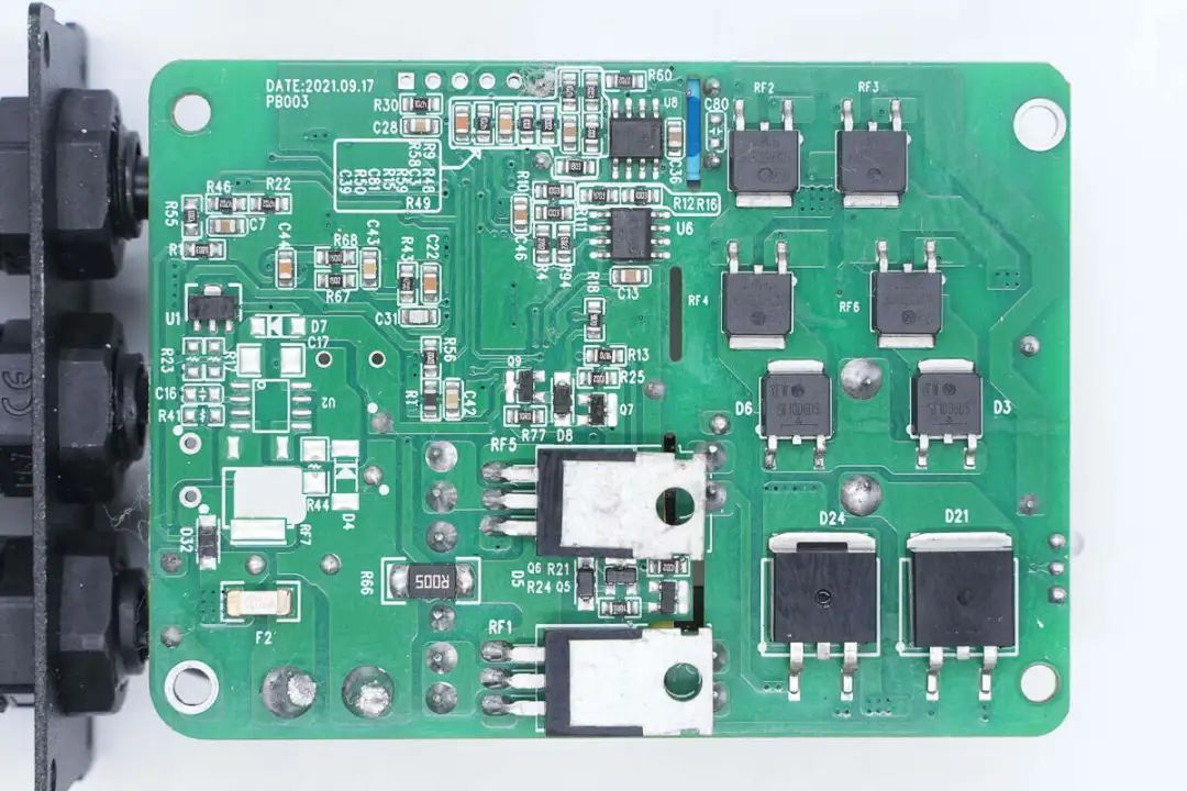
There are boost switch tubes and rectifier diodes under the thermal pad, and there are also output modulation tubes and two fast recovery diodes on the right side.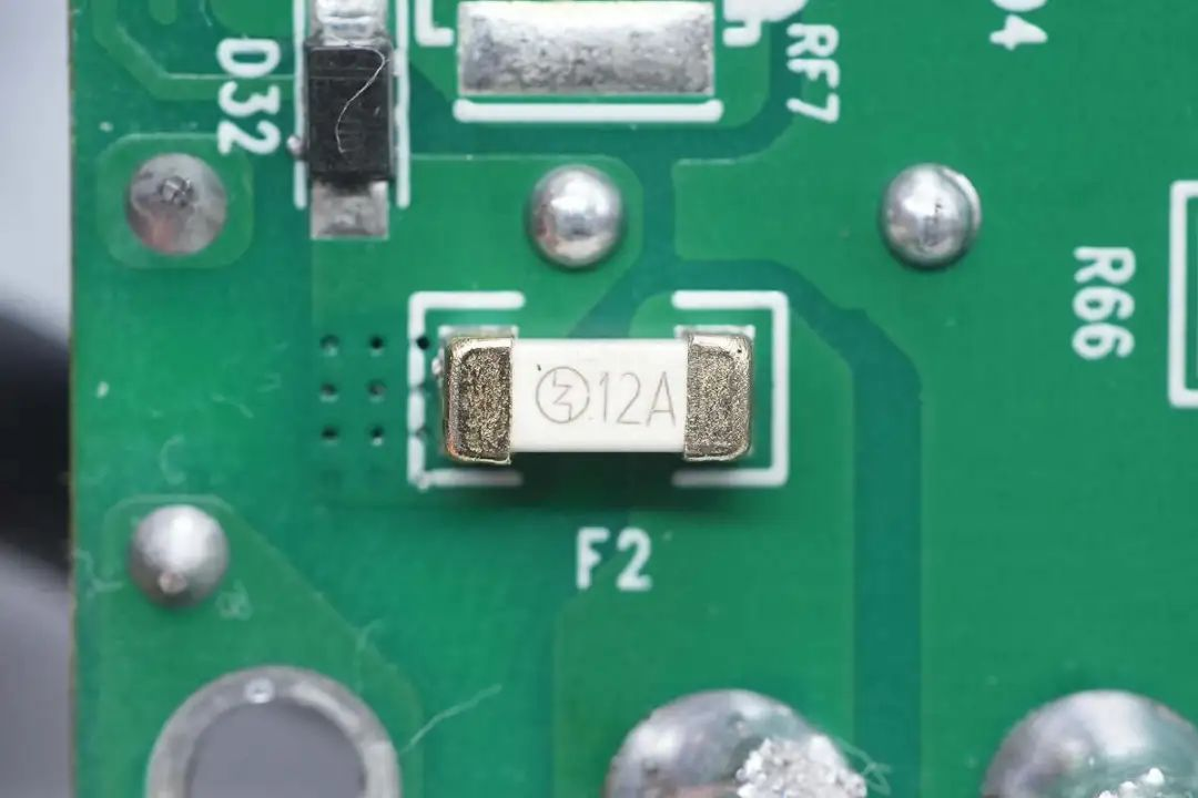
The specification of the DC input terminal patch fuse is 12A.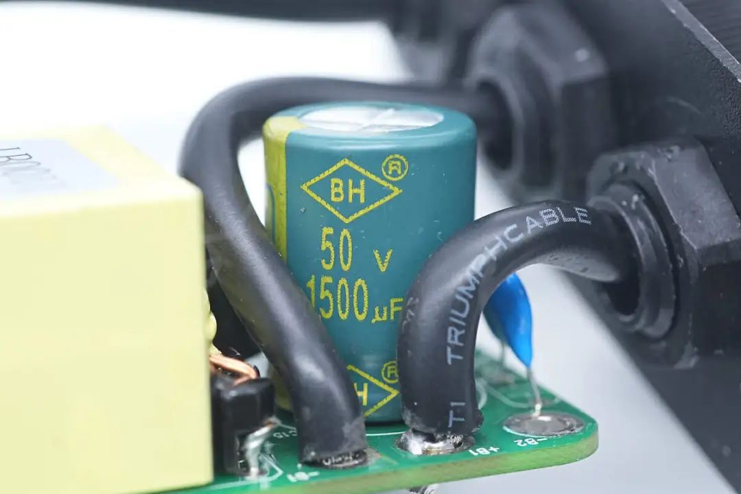
The input filtering capacitor specification is 50V1500 μF.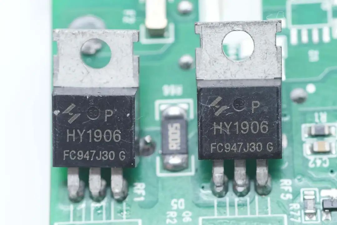
The boost switch transistor is from HUAYI Microelectronics, model HY1906P, NMOS, with a withstand voltage of 60V and a resistance of 6m Ω, packaged in TO220FB-3L.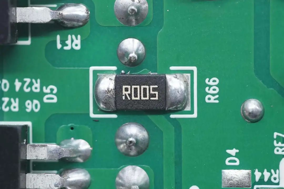
Close up of 5m Ω current sampling resistor.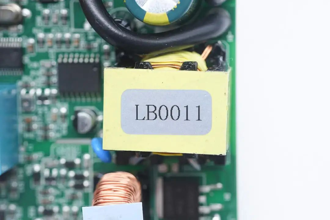
Close up of step-up transformer, magnetic core wrapped with tape insulation.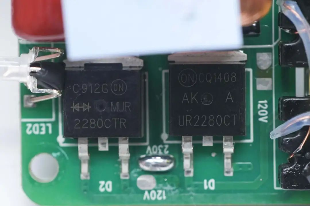
Two rectifier tubes are silk screened with MUR2280CTR and UR2280CT models, with specifications of 22A 800V. They are fast recovery diodes and packaged in TO-263.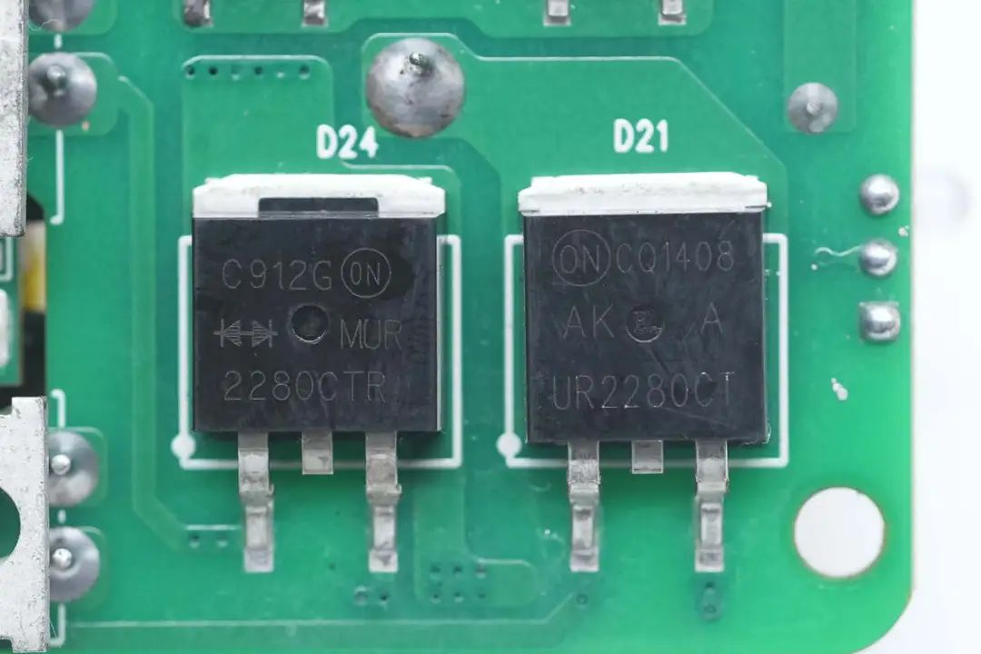
The other two rectifier tubes have the same silk screen printing.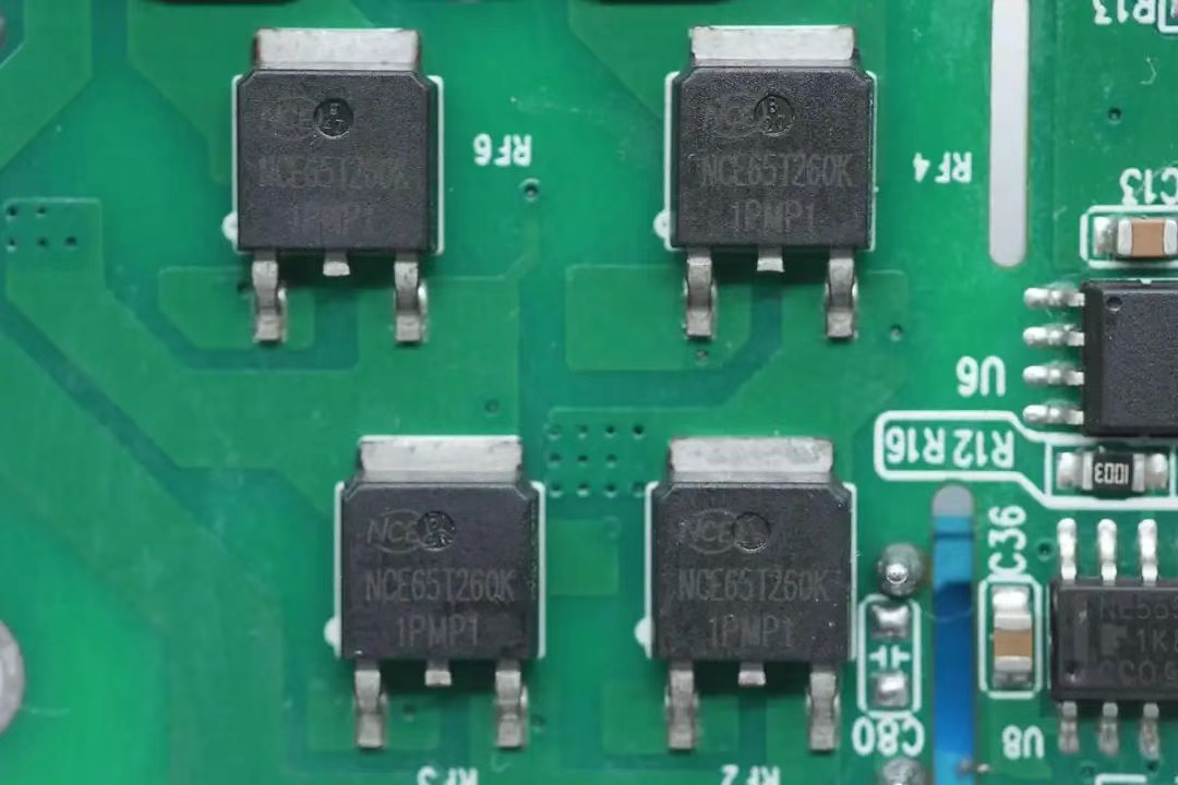
The four switching transistors used for output modulation are from New Clean Energy, model NCE65T260K, NMOS, withstand voltage 600V, conductivity 220m Ω, and packaged in TO-252.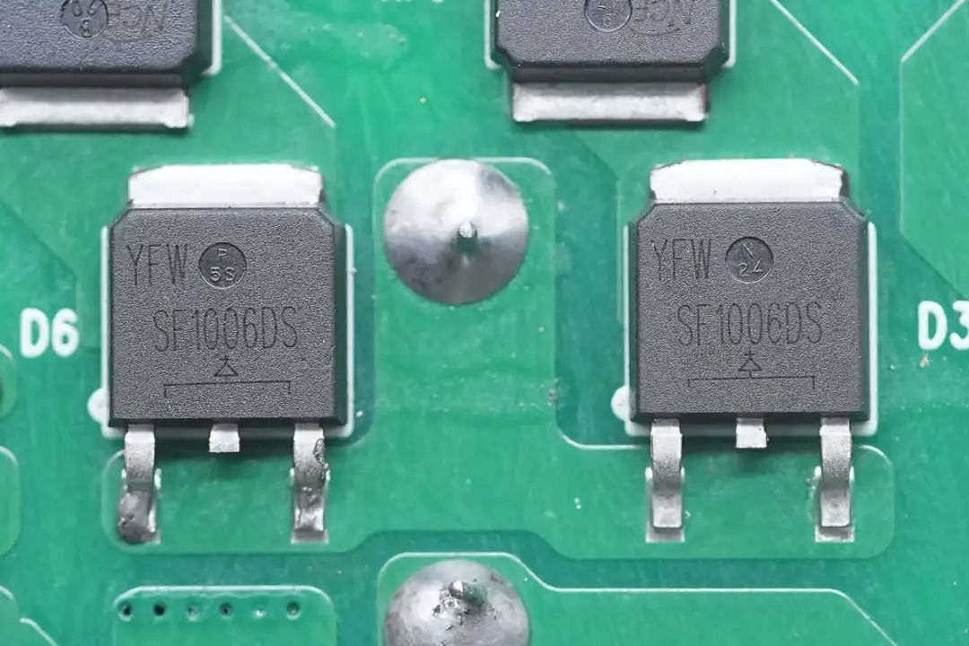
Two diodes from YFW Yufengwei, model SF1006DS, are ultra fast recovery diodes with a specification of 600V 10A and packaged in TO-252. YFW Youfeng Micro Brand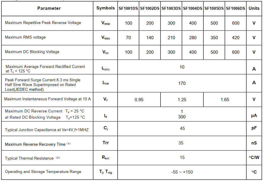
Yufeng Microelectronics "is a high-tech enterprise specializing in the research and development, production, and sales of semiconductor discrete devices. The company mainly produces and sells: ordinary rectifier diodes, fast recovery diodes, high-efficiency diodes, ultrafast recovery diodes, Schottky diodes, low voltage drop Schottky diodes, silicon carbide diodes, rectifier bridge stacks, fast recovery rectifier bridge stacks, Schottky bridge stacks, TVS transient suppression diodes, ESD electrostatic protection components, voltage regulators, transistors, thyristors, MOSFETs, and so on. For more details, please visit our official website www.yfwdiode.com.
Previous: YFW佑风微 MOSFET YFWG160N06NF PDFN5*6-8L Product substitution CSD18540Q5B
Next: YFW65N03DF 65A 30V PDFN33-8L markingYFW65N03DF MOSFET yfwdiode brand
