
Date:2025-06-19 Categories:Product knowledge Hits:408 From:Guangdong Youfeng Microelectronics Co., Ltd
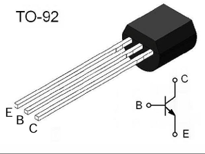
Bipolar Junction Transistors (BJTs): BJTs operate based on the principle of current control. Power transistors A small current flowing into the base terminal controls a much larger current between the collector and the emitter. When a positive voltage is applied to the base - emitter junction (forward - biased), electrons are injected from the emitter into the base. A small fraction of these electrons recombine with holes in the base, and the remaining electrons flow into the collector, creating a large collector current. The relationship between the collector current (IC), base current (IB), and the current gain (β) is given by IC=βIB
.
Metal - Oxide - Semiconductor Field - Effect Transistors (MOSFETs): MOSFETs are voltage - controlled devices. The voltage applied to the gate terminal creates an electric field that controls the conductivity between the source and the drain. When a sufficient positive voltage (threshold voltageVGS(th) is applied to the gate - source terminal, an inversion layer is formed in the channel region between the source and the drain, Power transistors allowing current to flow. The drain current (ID) is a function of the gate - source voltage (VGS) and the drain - source voltage (VDS).
Collector - Emitter Breakdown Voltage (
Drain - Source Breakdown Voltage (VDS(BR)): In MOSFETs, it represents the maximum voltage that the drain - source terminal can withstand without breaking down. Power transistors
Collector Current (IC) or Drain Current (ID): These are the maximum continuous currents that the transistor can carry. Operating the transistor beyond these current limits can lead to overheating and failure.
Power Dissipation (PD): It is the maximum power that the transistor can dissipate as heat. Power dissipation is calculated asPD=VCEICfor BJTs andPD=VDSIDfor MOSFETs. Excessive power dissipation can raise the junction temperature (TJ) of the transistor, and ifTJexceeds the maximum rated junction temperature (TJ(max)), the transistor will be damaged. Power transistors
3.2 Small - Signal Parameters
Current Gain (βfor BJTs): It represents the amplification factor of the transistor in the small - signal region. Power transistors A higher
Previous: Classification, Structure, and Principle of MOSFET
Next: Renesas tunable antenna varactor diodes for One-Seg broadcasting applications 1
