Circuit Analysis and Application Considerations
Date:2025-06-16 Categories:Product knowledge Hits:407 From:Guangdong Youfeng Microelectronics Co., Ltd
4. Circuit Analysis and Application Considerations
4.1 Half - Wave Rectifier Circuit
In a half - wave rectifier circuit, a single
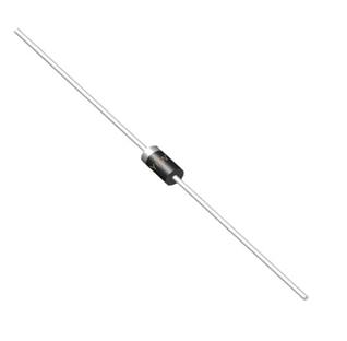
rectifier diode is used to convert AC to DC. During the positive half - cycle of the AC input, the diode is forward - biased and conducts, allowing current to flow through the load. During the negative half - cycle, the diode is reverse - biased and blocks the current. The output of a half - wave rectifier is a pulsating DC signal. Analyzing this circuit involves calculating the average output voltage, which is approximately 0.318 times the peak value of the input AC voltage, and understanding the ripple factor, which indicates the degree of variation in the DC output.
4.2 Full - Wave Rectifier Circuit
Full - wave rectifier circuits, such as the center - tapped and bridge rectifier configurations, use multiple diodes to rectify both the positive and negative half - cycles of the AC input. This results in a smoother DC output compared to a half - wave rectifier. In a bridge rectifier, for example,
rectifier diode,
four diodes are arranged in a bridge - like structure. During both the positive and negative half - cycles of the AC input, two diodes conduct at a time, ensuring continuous current flow through the load. Analyzing full - wave rectifier circuits requires considering the voltage drop across multiple diodes, the peak inverse voltage (PIV) across each diode, and the overall efficiency of the rectification process.
4.3 Filtering Considerations
To obtain a more stable and smooth DC output, filtering circuits are often used in conjunction with rectifier circuits.
rectifier diode,
Capacitor - input filters are commonly employed, where a capacitor is connected across the load. When analyzing the combined rectifier - filter circuit, the time constant (τ=RC, where Ris the load resistance andC is the capacitance) is an important parameter. A larger time constant results in a smoother DC output but also a slower response to changes in the input voltage or load current.
In conclusion, analyzing
rectifier diode comprehensively requires a deep understanding of their physical structure, electrical parameters, characteristic curves, and circuit applications. By carefully considering these aspects, engineers can select the appropriate rectifier diodes for specific power conversion tasks, optimize circuit performance, and ensure the reliability and efficiency of power supply systems.

Previous:
Classification, Structure, and Principle of MOSFET
Next:
Analysis of Fast Recovery Diodes
